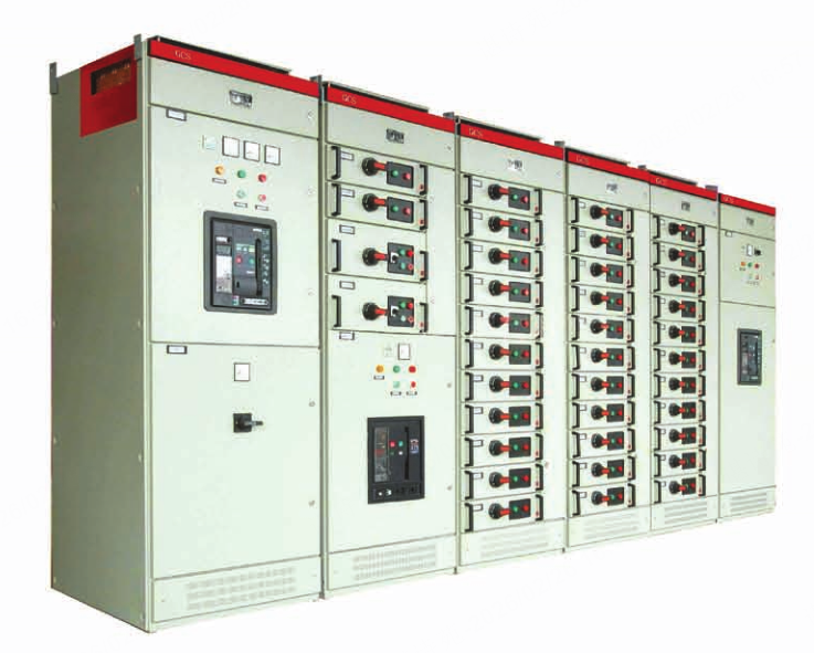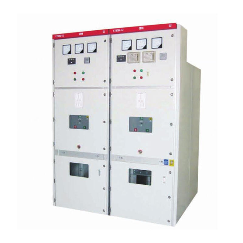
KYN28-12 (GZS1-12) Indoor Metal-Clad Withdrawable Switchgear
The KYN28-12 (GZS1-12) indoor metal-clad withdrawable switchgear is a complete power distribution unit designed for 3~10kV three-phase AC 50Hz single-bus and single-bus sectionalized systems. It is widely applied in power plants for power transmission from small and medium-sized generators, power distribution in industrial and mining enterprises, power receiving and transmission in secondary substations of power systems, and starting control of large high-voltage motors, serving core functions of control, protection and monitoring.
- Overview
- Recommended Products
The KYN28-12 (GZS1-12) indoor metal-clad withdrawable switchgear is a complete power distribution unit designed for 3~10kV three-phase AC 50Hz single-bus and single-bus sectionalized systems. It is widely applied in power plants for power transmission from small and medium-sized generators, power distribution in industrial and mining enterprises, power receiving and transmission in secondary substations of power systems, and starting control of large high-voltage motors, serving core functions of control, protection and monitoring.
This switchgear fully complies with international and national standards including IEC62271-200 and GB3906. It offers flexible configuration options, compatible with ABB VD4 vacuum circuit breakers and domestic VS1 vacuum circuit breakers to meet diverse project requirements.
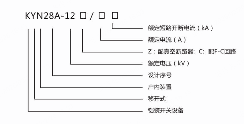
Model Explanation
Structural Features
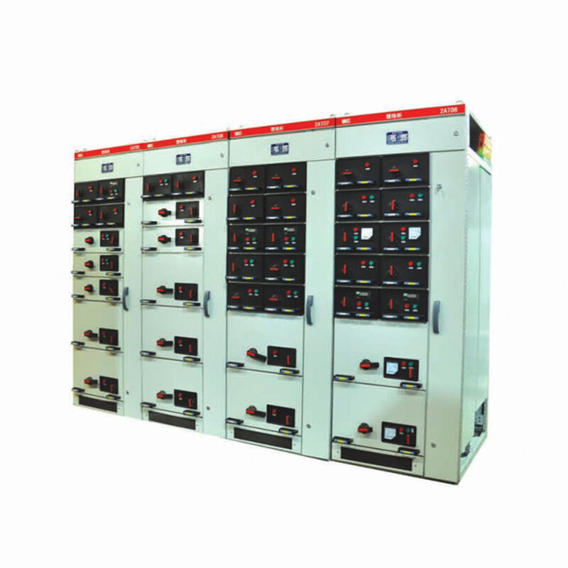
The KYN28-12 type high-voltage switchgear is a fully enclosed, metal-clad withdrawable indoor switchgear. The cabinet is fabricated from aluminum-zinc coated steel plates bent and assembled, featuring a fully enclosed structure. The interior is divided into four compartments by thin steel plates, connected with bolts: the upper section is the busbar chamber, the middle section is the trolley chamber, and the lower section is the cable chamber. Instruments and relays are installed in the instrument chamber at the front upper part of the cabinet, supporting overhead incoming/outgoing lines and left-right interconnection functions.
The trolley is welded from angle steel and steel plates, and is available in various types including circuit breaker trolley, voltage transformer & lightning arrester trolley, capacitor & lightning arrester trolley, station service transformer trolley, isolating trolley, and earthing trolley. The panel on the trolley serves as the cabinet door, with an observation window and lighting lamp on the upper part of the door, and functions to lock the trolley in working position, test position, and disconnected position.
Interlocks are installed on the upper and lower rear doors of the cabinet: the trolley can only be withdrawn after power failure; after the earthing switch is earthed, the lower rear door can be opened first, followed by the upper rear door. Before power-on, only after closing the upper rear door first and then the lower rear door can the earthing switch be opened, allowing the trolley to be inserted into the working position and preventing accidental entry into live compartments.
Operating Conditions
Ambient temperature: Upper limit +40°C, lower limit -25°C.
Altitude: ≤ 1000 m
Relative humidity: Daily average ≤ 95%, monthly average ≤ 90%.
Seismic intensity: ≤ Grade 8
The surrounding air should be free from obvious pollution by corrosive or flammable gases, water vapor, etc.
No severe pollution or frequent severe vibration; designed to meet Class I requirements under severe conditions.
When used under normal environmental conditions exceeding those specified in GB3906, it can be negotiated between the user and the manufacturer.
Main Technical Performance Parameters
| Rated Voltage | kV | 3; 6; 10 | |
| Maximum Operating Voltage | kV | 3.6; 7.2; 12 | |
| Rated Insulation Level | Power-frequency Withstand Voltage (1min) | kV | 42 |
| Lightning Impulse Withstand Voltage | kV | 75 | |
| Rated Frequency | Hz | 50 | |
| Rated Current of Main Busbar | A | 630; 1250; 1600; 2000; 2500; 3150 | |
| Rated Current of Branch Busbar | A | 630; 1250; 1600; 2000; 2500; 3150 | |
| 4s Thermal Stability Current (RMS) | kA | 16; 20; 25; 31.5; 40; 50 | |
| Rated Dynamic Stability Current (Peak) | kA | 40; 50; 60; 80; 100; 125 | |
| Protection Class | - | IP4X for enclosure; IP2X when compartment and circuit breaker room doors are open | |