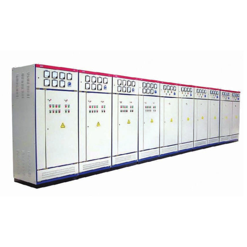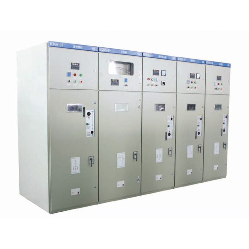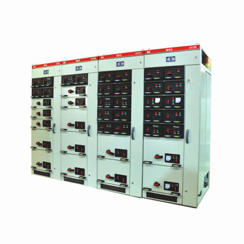
MNS Type Low Voltage Withdrawable Switchgear
The MNS low-voltage withdrawable switchgear is designed for three-phase AC power systems (50/60Hz) with a rated voltage of 660V and a rated current of 4000A or less, covering both three-phase four-wire and three-phase five-wire configurations.
- Overview
- Recommended Products
The MNS low-voltage withdrawable switchgear is designed for three-phase AC power systems (50/60Hz) with a rated voltage of 660V and a rated current of 4000A or less, covering both three-phase four-wire and three-phase five-wire configurations. It serves as a core device for power reception and distribution, and is extensively utilized in Power Centers (PC) and Motor Control Centers (MCC) across power plants, substations, industrial and mining enterprises, and high-rise buildings.
This product fully complies with the specifications of GB7251, ZBK36001, and IEC 439-1 (1992).
Operating Conditions
Ambient Temperature: -5°C to +40°C; the average temperature over any 24-hour period shall not exceed +35°C.
Relative Humidity: ≤50% at 40°C; higher humidity is permissible at lower temperatures (e.g., 90% at 20°C). Note that occasional condensation may form due to temperature fluctuations and should be considered in the installation design.
Installation Environment: Indoor use only; maximum altitude of the installation site: 2000m.
Site Requirements: Install in areas free from severe vibration, mechanical impact, and corrosive agents that could damage electrical components.
Structural Features
The basic frame of the switchgear adopts an assembled and combined structure. The KB-shaped steel sections are fastened together with self-tapping locking screws to form the basic frame. Then, according to the scheme changes, corresponding doors, sealing plates, partitions, mounting brackets, busbars, functional units and other parts are added to form a complete switchgear. The internal structure of the cabinet is galvanized, and can also be produced with aluminum-zinc coated steel plates, followed by passivation and phosphating treatment (1E = 25mm). The switchgear panel is processed from high-quality steel plates by CNC machine tools, and after pickling, phosphating treatment, it is electrostatically sprayed with plastic, which is corrosion-resistant and wear-resistant, with both firm mechanical strength and reliable grounding continuity.
The switchgear compartments can be divided into functional unit chambers, busbar chambers, and cable chambers. The functions of each unit are relatively independent, and the areas are strictly separated by continuous metal plates or flame-retardant plates for insulation, ensuring safe use and preventing the spread of accidents.
The horizontal busbars are installed horizontally to effectively reduce electrical and thermal stresses. There are 5 specifications for busbar cross-sections: 2 (30×10), 2 (60×10), 2 (80×10), 2 (100×10), and 4 (60×10), corresponding to current ratings of 1250A/2000A, 2500A, 3200A, and 4000A. The neutral grounding busbars N and PE are 60×10, and the drawer vertical busbars are 50×30×5 angle-shaped copper busbars. All busbars are tinned.
The MCC drawer cabinets are available in 5 specifications: 8E/4, 8E/2, 8E, 16E, and 24E (1E = 25mm). The drawers have connection position, test position, disconnected position, moving position, and separated position. Each drawer is equipped with a mechanical interlock with the switch. The drawer can only be pulled out or inserted when the switch is in the off position; when the switch is in the on position, the drawer cannot be pulled out. To prevent unauthorized operation, the operating mechanism can be padlocked to lock the switch in the off position. Functional unit drawers of the same specification can be easily interchanged, and each functional unit drawer corresponds to 16-32 pairs of auxiliary contacts, which can meet the needs of remote operation control, watt-hour metering, and automated monitoring systems interfaced with computers.
Technical Parameters
| Rated Operating Voltage | AC 380V, AC 660V |
| Rated Insulation Voltage | AC 660V, AC 1000V |
| Rated Current of Horizontal Busbar | 1250A, 2000A, 2500A, 3200A, 4000A |
| Rated Current of Vertical Busbar | 1000A |
| Maximum Current of Feeding Circuit | 2500A |
| Maximum Current of Drawer Circuit | 630A |
| Maximum Capacity of Control Motor | 320kW |
| Rated Frequency | 50, 60Hz |
| Peak Withstand Current of Horizontal Busbar (0.1s) | 105kA, 176kA |
| Short-time Withstand Current of Horizontal Busbar (1s) | 50kA, 80kA |
| Peak Withstand Current of Vertical Busbar (0.1s) | 105kA |
| Short-time Withstand Current of Vertical Busbar (1s) | 50kA |
| Rated Power-frequency Withstand Voltage (1min) | 2500V |
| Secondary Power-frequency Withstand Voltage (1min) | 2500V |
| Enclosure Protection Class | IP30, IP40 |
| Overall Dimensions | Width: 600, 800, 1000mm; Depth: 800, 1000mm; Height: 2200mm |