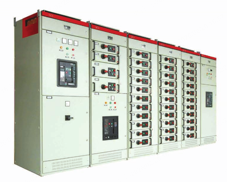
GCS Type Low Voltage Withdrawable Switchgear
The GCS low-voltage withdrawable switchgear was developed with the purpose of promoting technological progress in China's low-voltage distribution industry, accelerating the upgrading of low-voltage distribution switchgear assemblies, and protecting and developing the national industry, as mandated by the former Ministry of Electric Power Industry and the former Ministry of Machinery Industry.
- Overview
- Recommended Products
The GCS low-voltage withdrawable switchgear was developed with the purpose of promoting technological progress in China's low-voltage distribution industry, accelerating the upgrading of low-voltage distribution switchgear assemblies, and protecting and developing the national industry, as mandated by the former Ministry of Electric Power Industry and the former Ministry of Machinery Industry. In 1995, Senyuan Electric Co., Ltd. was commissioned to organize a joint design team from the two ministries to complete the design and development of the GCS low-voltage withdrawable switchgear. Currently, the product has gained initial recognition and been widely adopted across China.
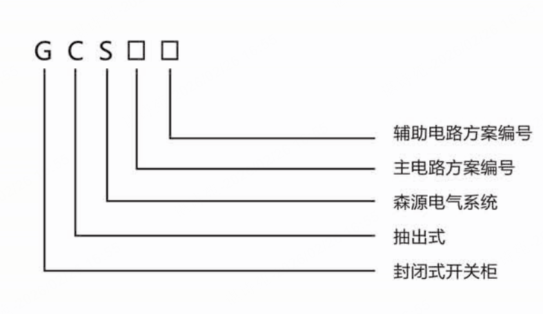
Model Explanation
Structural Features:
The main frame adopts 8MF type open-section steel, with mounting holes of 20mm and 10mm modules, and φ9.2 on both sides of the steel section, enabling flexible and convenient internal installation.
The main frame is available in two assembly forms: fully assembled structure and partially (side frames and cross beams) welded structure, for user selection.
The functional compartments of the device are mutually isolated, divided into functional unit chambers, busbar chambers, and cable chambers, with relatively independent functions.
The horizontal main busbars are arranged in a flat layout at the rear of the cabinet to enhance their resistance to electrodynamic forces, which is a fundamental measure to ensure the main circuit of the device has high short-circuit strength.
The design of the cable compartment facilitates convenient cable entry and exit both from the top and bottom.
Operating Conditions:
Ambient air temperature: -5°C to +40°C; the average temperature within any 24-hour period shall not exceed +35°C. If exceeded, derating operation is required based on actual conditions.
Indoor use only; maximum altitude of the installation site: 2000m.
Relative humidity: ≤50% at +40°C; higher humidity is allowed at lower temperatures (e.g., 90% at +20°C). Consideration should be given to the potential for occasional condensation due to temperature changes.
Installation inclination from vertical: ≤5°, and the entire cabinet row shall be relatively level (in compliance with GBJ232-82).
Installation site: Free from severe vibration, impact, and corrosive agents that could damage electrical components.
Special user requirements can be negotiated with the manufacturer.
Main Technical Parameters:
| Rated Voltage of Main Circuit (V) | AC 380 (400), (600) | |
| Rated Voltage of Auxiliary Circuit (V) | AC 220, 380 (400); DC 110, 120 | |
| Rated Frequency (Hz) | 50 (60) | |
| Rated Insulation Voltage (V) | 660 (1000) | |
| Rated Current (A) | Horizontal Busbar | ≤4000 |
| Rated Current (A) | Vertical Busbar (MMC) | 1000 |
| Rated Short-time Withstand Current of Busbar (kA/1s) | 50, 80 | |
| Rated Peak Withstand Current of Busbar (kA/0.1s) | 105, 176 | |
| Power-frequency Test Voltage (V/1min) | Main Circuit | 2500 |
| Power-frequency Test Voltage (V/1min) | Auxiliary Circuit | 1760 |
| Busbar | Three-phase Four-wire System | A, B, C, PEN |
| Busbar | Three-phase Five-wire System | A, B, C, PE, N |
| Protection Degree | IP30, IP40 | |