 EN
EN

When a transformer failure in a Bangkok commercial district plunged 12 buildings into darkness for six hours, the investigation revealed that the low voltage distribution panel in the affected substation had been operating at 94 percent of its rated capacity for three consecutive summers — but no one had visibility into the loading trend. The failure was predictable, preventable, and entirely a consequence of monitoring gaps at the distribution level. Urban power supply reliability is ultimately determined not by generation capacity or transmission infrastructure, but by the last kilometer of the electrical network — the low voltage distribution system that delivers power to every building, every elevator, and every life-safety system.
The Critical Role of LV Distribution in Urban Networks
The Interface Between Grid and End User
Low voltage distribution represents the final stage of the power delivery chain, stepping voltage down from medium-voltage levels of 10 kV or 20 kV to utilization voltages of 400/230 volts through distribution transformers. This transformation occurs inside compact substations, pad-mounted transformers, or building-integrated substations dispersed throughout the urban fabric. From the transformer's low voltage terminals, power flows through the main LV switchgear — typically a withdrawable-type assembly such as GCK, GCS, or MNS — where it is distributed across multiple feeder circuits serving different building zones, electrical loads, and tenant spaces. A failure at any point in this distribution path disconnects everything downstream. There is no redundancy for most LV circuits because the cost of duplicating distribution infrastructure for every building is prohibitive. This single-point-of-failure characteristic makes the quality of low voltage distribution design and equipment directly proportional to urban power supply reliability.
Monitoring and Smart Grid Integration
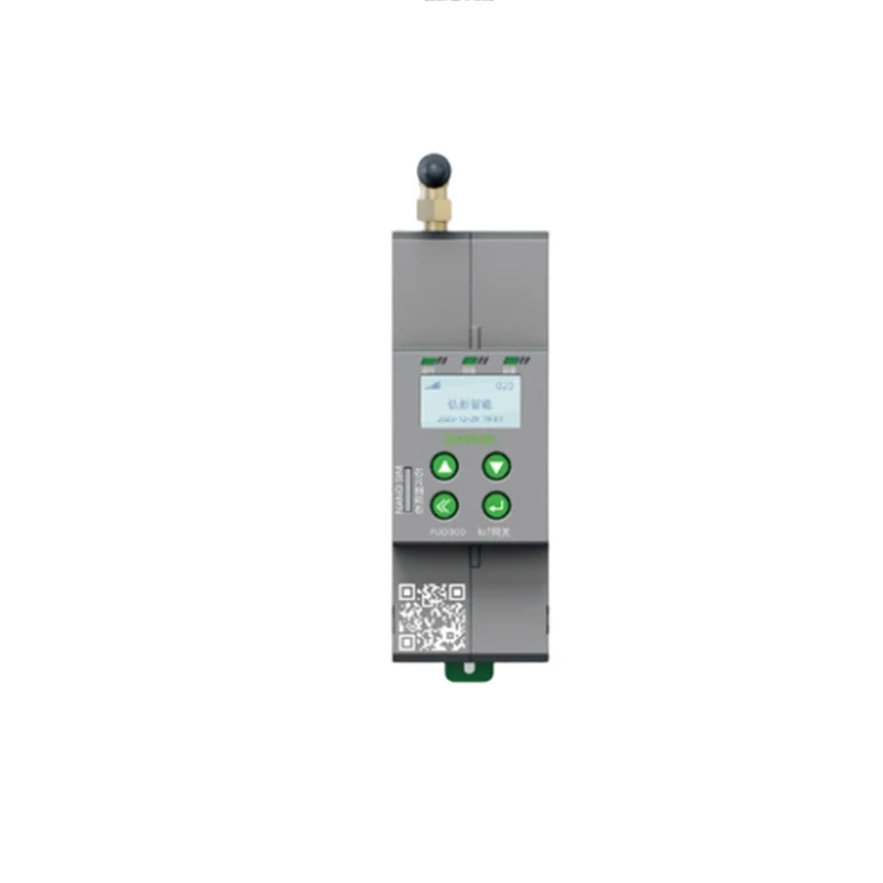
Traditional LV distribution panels provided circuit protection and nothing else — breakers tripped when faults occurred, and operators learned about problems when building occupants called to complain. Smart low voltage distribution integrates monitoring at every level of the hierarchy. Intelligent circuit breakers with embedded metering report current, voltage, power factor, and energy consumption per feeder to a central energy management platform. Temperature sensors on busbar joints and breaker terminals detect developing hot spots before they become failures. The platform aggregates this data across all distribution points in a facility or across an urban utility network, providing operators with real-time visibility into loading patterns, power quality metrics, and equipment health indicators. This data transforms maintenance from calendar-based schedules to condition-based interventions — a breaker approaching its mechanical endurance limit is replaced before it fails, a busbar connection trending toward excessive temperature rise is re-torqued during a planned outage rather than becoming an emergency repair.
Resilience Through Architecture and Equipment Quality
Urban power supply resilience depends on design choices made long before equipment is installed. The selection of withdrawable switchgear over fixed designs enables breaker replacement without de-energizing the entire panel — a feature that converts what would be a multi-hour outage into a brief switching operation. Form 4 internal separation as defined by IEC 61439 physically segregates busbars, functional units, and cable terminations into separate compartments, preventing a failure in one section from propagating to adjacent sections. For critical urban facilities — hospitals, data centers, transit systems — low voltage distribution incorporates automatic transfer switches that transfer load to backup generators or alternate utility feeders within seconds of a supply interruption. These switches must coordinate with downstream protection devices to ensure that inrush currents from transformers and motors restarting after transfer do not cause nuisance tripping.
Frequently Asked Questions
What voltage levels define low voltage distribution?
Low voltage distribution operates at voltages up to 1,000 volts AC as defined by IEC standards. The most common utilization voltages are 400/230 volts three-phase in IEC markets and 480/277 volts or 208/120 volts in North American markets.
How do smart LV panels differ from conventional distribution boards?
Smart panels incorporate intelligent circuit breakers with embedded metering and communication modules, enabling real-time monitoring of electrical parameters per circuit. The data feeds into energy management platforms that provide load trending, power quality analysis, and predictive maintenance alerts — capabilities absent from conventional protection-only panels.
What is the economic impact of low voltage distribution failures in urban areas?
A single hour of downtime in a commercial office building typically costs 50,000 to 500,000 in lost productivity and operational disruption. For industrial facilities with continuous processes, costs can exceed $1 million per hour. These figures justify significant investment in distribution system reliability.
How does harmonics from modern loads affect LV distribution equipment?
Nonlinear loads — LED lighting, variable frequency drives, computer power supplies — generate harmonic currents that cause additional heating in transformers, neutral conductors, and busbar connections. K-factor rated transformers and oversizing neutral conductors are common mitigation strategies in buildings with high concentrations of electronic loads.
What role does low voltage distribution play in building energy efficiency?
LV distribution panels with circuit-level metering enable energy managers to identify inefficient loads, allocate energy costs to tenants or departments, and verify the performance of energy conservation measures. This granular visibility is a prerequisite for achieving certifications such as LEED and BREEAM.
How are low voltage distribution systems tested before commissioning?
Factory testing includes dielectric voltage withstand tests, insulation resistance measurements, protective device operation verification, and temperature rise tests on busbar systems according to IEC 61439. On-site commissioning adds primary and secondary injection testing of protection relays, polarity and phase rotation checks, and functional testing of interlocking and automation schemes.