 EN
EN

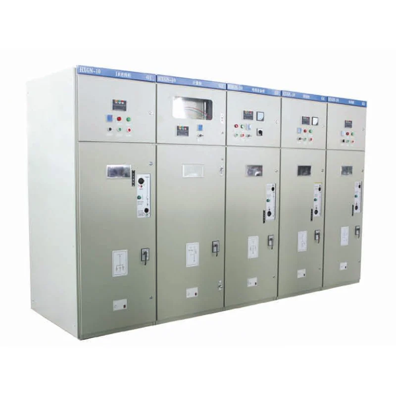
An electrical engineer at a food processing plant discovered that a single overload trip on a feeder breaker had cascaded through the upstream protection, shutting down the entire packaging line — not because the fault was catastrophic, but because the protection coordination study had been neglected during the original low voltage distribution design. The production loss from that four-hour shutdown exceeded the cost of a proper coordination study by a factor of 20. Low voltage distribution design may not be visible to building occupants or production managers, but when it fails, the consequences cascade through every system that depends on electrical power.
Fundamental Design Principles
Load Calculation and Diversity Factors
Every low voltage distribution design begins with an accurate load schedule — a documented list of every circuit, its connected load in kilowatts or kilovolt-amperes, and its expected operating characteristics. Three-phase loads such as motors, HVAC compressors, and industrial heating elements are balanced across phases to minimize neutral current and voltage imbalance. Single-phase loads — lighting circuits, convenience receptacles, office equipment — are distributed across the three phases with a target imbalance of less than 15 percent between the highest and lowest loaded phase. Diversity factors recognize that not all connected loads operate simultaneously at full rating. A commercial building's lighting load diversity factor might be 0.9, while socket outlet circuits in office areas might apply 0.3 to 0.5, reflecting the reality that only a fraction of receptacles serve active equipment at any given time. Applying appropriate diversity factors prevents oversizing of transformers, main busbars, and upstream switchgear — oversizing that adds cost, increases physical footprint, and may actually reduce energy efficiency because transformers operate less efficiently at light loading.
Protection Coordination and Selectivity
Selective coordination means that when a fault occurs, only the protection device immediately upstream of the fault operates — the breaker feeding the faulted circuit trips, while all upstream breakers remain closed. Achieving this requires a coordination study that plots the time-current characteristic curves of every protection device in the distribution hierarchy, from the main incomer down to the final circuit breakers. For molded case circuit breakers in low voltage switchgear, coordination is typically achieved by selecting breakers with different instantaneous trip settings or by introducing time delays in upstream devices. In withdrawable switchgear designs such as MNS or GCS type low voltage panels, breakers can be configured with electronic trip units that offer adjustable long-time, short-time, and instantaneous protection settings — flexibility that simplifies coordination compared to fixed thermal-magnetic trip units. Ground-fault protection deserves particular attention in low voltage distribution design. A ground fault on a 400-amp feeder may not draw enough current to activate the phase overcurrent protection, allowing the fault to persist undetected. Dedicated ground-fault relays or breakers with integral ground-fault protection provide the sensitivity needed to detect and clear these hazardous conditions.
Busbar and Thermal Management
The main busbar system within a low voltage switchgear assembly carries the aggregated load current of all connected feeders. Busbar cross-sectional area is selected based on continuous current rating, short-circuit withstand capability, and temperature rise limits defined by IEC 61439 or equivalent standards. Copper busbars are standard for most applications, with aluminum used where weight and cost are prioritized provided that proper bi-metallic connections prevent galvanic corrosion at transition points. Thermal management within the switchgear enclosure directly affects busbar and breaker performance. Natural convection cooling through ventilation louvers is adequate for most installations, but assemblies installed in high-ambient environments or operating near their rated current continuously may require forced ventilation. The standard temperature rise limit for busbar connections is 70 Kelvin above ambient for bare copper and 65 Kelvin for tin-plated connections — exceeding these limits accelerates oxidation, increases contact resistance, and creates a self-reinforcing cycle of degradation.
Frequently Asked Questions
What is the difference between fixed and withdrawable low voltage switchgear?
Fixed switchgear has circuit breakers permanently mounted on the busbar system requiring de-energization for replacement. Withdrawable designs mount breakers on carriages that can be racked out for maintenance without de-energizing the entire panel, reducing downtime during breaker replacement or testing.
How is the short-circuit rating of a low voltage distribution panel determined?
The panel's short-circuit withstand rating must exceed the maximum prospective fault current at its point of installation. Typical ratings range from 25 kA to 100 kA for one second, calculated based on transformer impedance, cable impedance from the supply source, and motor contribution from connected rotating loads.
What standards apply to low voltage switchgear design?
IEC 61439 governs low voltage switchgear and controlgear assemblies, covering type testing and routine verification. Specific parts address distribution boards for operators, power switchgear for skilled persons, and busbar trunking systems. IEC 60947 covers individual switching and protection devices.
How does arc flash hazard influence low voltage distribution design?
Arc flash studies calculate the incident energy at each point in the distribution system, informing the selection of personal protective equipment and influencing design decisions such as remote racking of withdrawable breakers, arc-resistant switchgear construction, and zone-selective interlocking to reduce arc clearing time.
What role do neutral and ground conductors play in system design?
The neutral conductor carries unbalanced three-phase return current and must be sized accordingly — in systems with significant harmonic loads from electronic equipment, the neutral may carry current exceeding the phase conductors, requiring oversizing. The protective earth conductor provides the fault current return path and must be sized to withstand prospective fault current for the duration required for protection operation.
How often should protection coordination studies be reviewed?
Coordination studies should be reviewed whenever significant loads are added or removed, when utility supply characteristics change, or at intervals not exceeding five years. Changes in upstream protection settings by the utility, degradation of cable insulation over time, and equipment replacement with different characteristics all affect the validity of the original coordination analysis.