 EN
EN

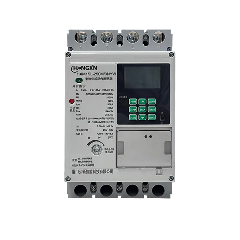
A solar installer in Southern Europe commissioned a 100 kW rooftop PV system only to discover that the inverter was clipping output at 82 kW during peak sunlight hours. The undersized inverter was wasting nearly 20 percent of the array's potential generation — an error that could have been avoided by understanding the DC-to-AC conversion process and correctly matching inverter capacity to array characteristics. The inverter is the intelligence center of any photovoltaic installation, and its conversion technology determines how much of the solar energy captured by the panels actually reaches the building's electrical system or the utility grid.
The DC-to-AC Conversion Process
Maximum Power Point Tracking
Photovoltaic panels produce DC power at a voltage and current that vary continuously with solar irradiance and cell temperature. For any given set of conditions, there exists a single operating point — the maximum power point — where the product of voltage and current is maximized. A maximum power point tracking algorithm embedded in the inverter's control system continuously adjusts the input impedance seen by the PV array to operate at this optimal point. Perturb-and-observe is the most common MPPT algorithm: the controller makes a small adjustment to the operating voltage, measures whether output power increased or decreased, and moves in the direction that produced improvement. Modern string inverters incorporate multiple independent MPPT channels, each connected to a separate string of PV modules — this architecture prevents shading on one string from dragging down the performance of unshaded strings sharing the same tracking channel. The MPPT efficiency — the percentage of available array power the algorithm actually captures — typically exceeds 99 percent for well-designed systems under stable irradiance conditions.
Power Switching and Waveform Generation
The DC power captured by the MPPT stage flows to the inverter's power conversion stage, where semiconductor switches — typically insulated-gate bipolar transistors rated for 600 to 1,200 volts — convert the DC input into a pulsed output that approximates a sinusoidal AC waveform. Pulse-width modulation controls the switching sequence: by varying the width of each voltage pulse according to a reference sine wave, the average output voltage at each point in the cycle matches the desired sinusoidal value. The switching frequency, typically 16 to 20 kilohertz for modern inverters, is high enough that the output filter — a combination of inductors and capacitors — can smooth the pulsed waveform into a clean sine wave with total harmonic distortion below 3 percent. This filtering stage is critical because excessive harmonic content in the inverter output can cause overheating in connected motors, interference with sensitive electronic equipment, and rejection by grid protection relays if the inverter is exporting power to the utility.
Grid Synchronization and Transformer Options
Grid-connected inverters must synchronize their output voltage, frequency, and phase angle with the utility supply before connecting. The inverter's control system monitors grid voltage through sensing circuits and adjusts the switching pattern to match within tight tolerances — typically ±0.1 hertz for frequency and within a few degrees for phase angle. Transformer-based inverters use a low-frequency transformer to provide galvanic isolation between the DC and AC sides, offering inherent protection against DC current injection into the grid and simplifying grounding system design. Transformerless inverters eliminate the iron-core transformer, reducing weight, physical size, and cost while improving conversion efficiency by 1 to 2 percent. The trade-off is that transformerless designs require more sophisticated DC leakage current detection and suppression circuits to meet grid connection standards, and are typically limited to ungrounded PV array configurations to prevent capacitive leakage paths through the panel frames to ground.
Efficiency and Environmental Factors
Modern inverter peak efficiency reaches 97 to 99 percent under optimal conditions, but the European efficiency rating — a weighted average that reflects real-world operating conditions — provides a more realistic performance indicator. The EU efficiency formula applies weightings to conversion efficiency at different load levels: 3 percent weighting at 5 percent load, 6 percent at 10 percent, 13 percent at 20 percent, and progressively higher weightings up to full load, reflecting the actual distribution of operating conditions across a typical solar day. Efficiency drops at low load because the inverter's internal power consumption — for control electronics, cooling fans, and switching losses — becomes significant relative to throughput. Selecting an inverter sized so that the array's typical operating range falls within the inverter's peak efficiency band — typically 30 to 70 percent of rated capacity — maximizes annual energy yield.
Frequently Asked Questions
What is the difference between string inverters and microinverters?
String inverters connect multiple PV modules in series to a single inverter, typically rated 1 to 100 kW. Microinverters mount one small inverter per individual module, converting DC to AC at the panel level. Microinverters eliminate single-point failure risk and mitigate shading losses but cost more per watt installed.
How does MPPT handle rapidly changing cloud conditions?
Advanced MPPT algorithms incorporate predictive tracking that anticipates irradiance changes based on recent power trends rather than blindly perturbing and observing. In partly cloudy conditions where irradiance can fluctuate 50 percent in seconds, these algorithms maintain tracking accuracy above 98 percent.
Why do grid codes require inverters to have anti-islanding protection?
Anti-islanding protection ensures the inverter disconnects from the grid within two seconds of a utility outage, preventing the PV system from energizing a section of the grid that utility workers assume is de-energized. This is a mandatory safety requirement in all grid connection standards including IEEE 1547 and IEC 62116.
What causes inverter clipping and how is it avoided?
Clipping occurs when the DC input power from the PV array exceeds the inverter's maximum AC output rating. The inverter limits output to its rated capacity, discarding the excess energy. Proper sizing matches the array's peak DC power — typically 1.1 to 1.3 times the inverter's AC rating — to the inverter capacity, accepting slight clipping during rare peak conditions to avoid oversizing the inverter.
How does ambient temperature affect inverter performance?
Inverter efficiency decreases as internal component temperature rises, and inverters typically derate output power when ambient temperature exceeds 40 to 45°C. Installation in shaded, well-ventilated locations rather than direct sunlight on rooftops can reduce operating temperature by 10 to 15°C and improve annual energy yield by 2 to 4 percent.
Can inverters provide reactive power support to the grid?
Modern grid-connected inverters can operate at power factors other than unity, injecting or absorbing reactive power as commanded by the grid operator or a site controller. This capability, mandated by updated grid codes in many jurisdictions, enables PV systems to contribute to grid voltage regulation rather than simply exporting active power.