Evaluating Electrical Systems for Smart Circuit Breakers
Evaluating your electrical system before a smart circuit breaker installation is necessary for hazard prevention and performance optimization. Professional assessments can reveal problems of incompatibility and safety.
Compatibility of Panels, Age of Wiring, and Spatial Considerations
Check your current electrical panel before smart breaker installation. Many older panels can be less suited for modern technology, as they may lack enough space for required upgrades or the necessary type of busbar. Some older models may need expansions or complete replacements. When examining the wiring, consider its age and the type of material used. Pre-1970s aluminum wiring is inadequate and poses safety risks. The same is true for knob and tube wiring. Outdated electrical code wiring is often required to be completely replaced. Be sure that internal components are sufficient to handle loads of connected smart devices and will be compatible with the mounting system that will be installed with the new breaker.
Load Analysis and Proper Smart Circuit Breaker Sizing (MCB vs. MCCB).
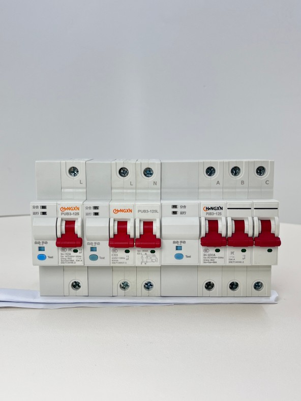
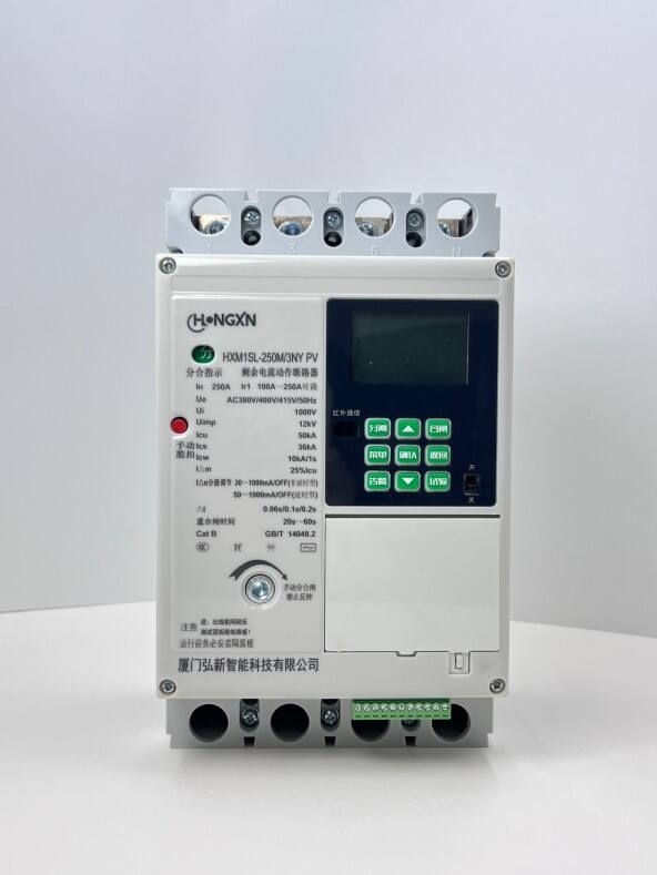
To achieve the best accuracy, do load calculation following the guidelines found in NEC Article 220, rather than just pulling nameplate numbers. This is fundamental for selecting the appropriate breakers. Miniature Circuit Breakers are adequate for most household circuits that do not exceed 125 amps, but for any main service panel/subpanel, or large applications such as electric vehicle charging stations or large HVAC systems, we will need to use Molded Case Circuit Breakers. Sizing a breaker too large will lead To nuisance tripping and other operational problems, while sizing it too small will cause the breaker to overheat and fail. The best approach is to determine sizing based on actual usage during peak loads rather than worst case operational scenarios.
Neutral and Earth Connection Verification, and Capacity Headroom
Your inspection of electrical systems should include checking for any signs of corrosion or overheating on the neutral conductor, as well as checking whether there is sufficient capacity as the conductor may be undersized for the task. This is particularly crucial for split-phase 120/240V systems as severe issues may arise as neutral conductors become overloaded due to unbalanced loading. Also, be sure to complete grounding tests as stipulated in IEEE 142. Measurements greater than 25 ohms means that the earth connection is ineffective, increasing the risks of electric shock and damage to equipment. Finally, ensure that the panel has a minimum of 20% headroom remaining after all devices are installed. Headroom allows for the safe addition of devices later, as well as allowing communication modules to operate without causing performance issues due to voltage drops.
Safe and Code-Compliant Installation of Smart Circuit Breakers
Wiring Differences: Power, Communication, and Neutral Connections
Smart circuit breakers require three types of wiring. There’s the line/load power connection, the neutral wire, and then, of course, the communication wire. Smart circuit breakers have their own electronics and sensors, which means they need power as well. Because of this, standard circuit breakers don’t require this third connection. So, if a neutral wire is present, it’s likely that the rest of the wiring will be rendered useless. For wiring, stick with UL listed standards with black as hot, blue as neutral, and yellow/green as a ground fill. For communication wire, use twisted shielded paired wiring to protect from electromagnetic interference. Also, make sure to torque the connections as the manufacturer states. The Electrical Safety Foundation states that not torquing wire connections, which causes terminal arcing, and heat, accounts for about 40% of all circuit breaker field failures.
Essentials for Lockout-Tagout, PPE, and NEC/IEC Compliance
Before attempting any electrical work, you need to ensure that the electricity is turned off, and that there is no remaining voltage present in any of the panel conductors by using a CAT IV multimeter. It is essential that you comply with the Lockout-Tagout procedures of OSHA standard 1910.333, and ensure that the main and branch circuits have been de-energized by a power source. It is also important to wear a minimum Class 00 glove with leather insulation, and an arc flash face shield that is rated for the incident energy levels of the panel. Recent data by OSHA indicates that the appropriate personal protective equipment reduces electrical injuries by approximately 72%. When operating on North American panels, ensure that the breakers are able to interrupt fault currents in accordance with NEC 110.9. For panels in the rest of the world, ensure that the equipment is in accordance with components of the thermals that are 60947-2, and ensure that the IP20 related short circuits are adequately coordinated to the enclosure.
The “Big 3” Mistakes in Installing Electrical Equipment - And How to Fix Them
Neglecting the neutral wire: 45% of the malfunctions of smart breakers are due to absent neutral wires, shared neutrals, or neutrals that are not the right size. Solution: a neutral bus bar should be installed at the same time as the panel upgrade, and the neutral wire should be verified for continuity and gauged to be 10-12 AWG before the panel is energized.
Interference: When data wires are run in the same direction as conductors with high current, there is a lot of induced noise. For interference to be reduced, a separation of 6 inches should be maintained, or ferrite cores and a grounded metallic conduit should be used to shield the wires.
Neglected Firmware Updates: Firmare that hasn't been updated accounts for 30% automation failures. Mitigation: Before commissioning, do all firmware updates that are required by the manufacturer. Don't trust the system to do updates itself after the system is installed. Do infrared thremography as soon as the system is energized to locate troubled siutations involving untightend connections and harmonic distortion.
Setting Up Your Smart Circuit Breaker for Remote Monitoring and Control
Wi-Fi Network and App (Tuya, SmartThings, Matter) Pairing
Position the router or mesh node as close to the electrical panel as possible, within approximately 30 feet. Make sure they are not obstructed by anything that is made of metal, thick concrete walls, etc. as they restrict the 2.4 GHz signals that smart breakers use. When you pair the smart breakers with compatible systems, it is better to use only the 2.4 GHz band as many smart breakers only support the 2.4 GHz Wi-Fi. Furthermore, ensure your Matter devices have the updated Matter 1.3 for better connectivity. The trouble many users encounter is due to inadequate device support, hence it is advisable to thoroughly prepare everything beforehand. Ensure your system has the correct voltage that the breaker is rated for (Usually the house coming voltage is 120/240V split phase) to avoid unnecessary inconveniences.
Calibration, Firmware Updates, and Setting Up Real-Time Alerts & Active Scheduling
As with all sensors, current sensors should be professionally calibrated. Responding with ±3% accuracy during calibration requires stable load conditions, and an external calibrated clamp meter is a required check. Automatic firmware updates should be enabled to rapidly close security vulnerability patches. Approximately 66% of reported cyber incidents in distributed energy systems involve grid edge devices with outdated firmware, according to last year’s Grid Security Report. Real-time alerts are recommended and issued for overloads exceeding 15 minutes and 110% of volumetric capacity, cycling of less than 90% of operational voltage, and cycling of devices less than 3 times in an hourly period. Modern equipment includes programmable load-shedding capabilities that can be set to turn off load devices during costlier time-of-use peak hour periods. With these setups, manual adjustments are reduced by 40%, and they remain fully compliant with the current NEC 210.20(A) cap on continuous loads.
FAQ
What is the significance of the evaluation of the electrical panel before the installation of the smart circuit breakers?
Evaluating the electrical panel is vital to ensure proper integration with advanced features. Older electrical panels can have inadequate spacing and configurations, which means installation pre-requisites, like panel expansion and alterations, may be necessary before the integration of smart breakers.
What is the importance of load analysis for smart circuit breakers?
Smart circuit breakers may be sized properly by performing a load analysis as specified in NEC Article 220. This is meant to avoid issues like false trips and overheating by sizing breakers based on actual use as opposed to worst case scenario situations.
What steps can be taken to ensure smart circuit breakers are installed safely and in accordance with the law?
If you follow procedures like Lockout-Tagout and ensure that you are complying with NEC/IEC standards that should be enough. Just wear your required PPE and check that the breakers are rated for sufficient interrupting capacity for the fault currents.
What are some of the top mistakes made during the installation of smart circuit breakers?
Ignoring the neutral wire, skipping interference, and not updating firmware prior to commissioning are the top mistakes. To avoid system complexity, these practices should be followed.